Showing posts with label HA. Show all posts

Saturday, December 29, 2018

Security: Palo Alto Virtual Appliance HA Test

I wanted to test the High Availability features of Palo Alto Virtual Appliance (version - PAN OS 8.0) firewall, so I have deployed two appliances named PA-HA-01 and PA-HA-02 in a single host running ESXi 6.7 managed by a vCenter Appliance 6.7. This is just a simple Active-Passive HA setup with successful tests of configuration synchronization.

It is better to run those two appliances in different hosts for better availability but I have to manage with a single host, so I have made some changes in the vSwitch which I will discuss below.

Palo Alto HA feature requires two separate control and data networks to be setup. There is also the management network for the appliances. So I have setup a vSwitch named vSwitch2 in the host without any uplink physical ports from the server. And then I created a Port Group named PA-HA. The above mentioned data and control network will be utilizing this Port Group (PA-HA). It should be noted that we are not using any physical uplink ports in the vSwitch2 configuration, so the data and control networks from both the appliances will communicate each other through the vSwitch2. 

In production environments, where two virtual appliances are deployed in two different hosts, the HA data and control networks would communicate with each other through dedicated physical uplink ports. 


Server Configuration


vCenter: vc2.prv.com
ESXi host: srv.prv.com

Virtual Appliance Configuration

PA-HA-01


Management IP: 192.168.200.3 (vNIC 1)
Primary Control Link IP: 192.168.5.3 (vNIC 3)
Primary Data Link IP: 192.168.6.3 (vNIC 4)
Device Priority: 77

PA-HA-02


Management Network: 192.168.200.4 (vNIC 1)
Primary Control Link IP: 192.168.5.4 (vNIC 3)
Primary Data Link IP: 192.168.6.4 (vNIC 4)
Device Priority: 100

We can also setup secondary control and data links but I have omitted them as this is optional.


We can see in the above image the details of the PA-HA-01 Appliance.


Then the details of the PA-HA-02 Appliance.

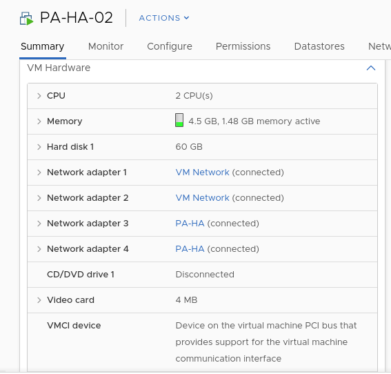
The images below show the details of the Virtual Machine's hardware. Network adapter 1 is used by the Palo Alto management interface which we will access through the browser. Network adapters 3 and 4 are Control and Data Links respectively for both the appliances.


Interface Configuration


So now we access the web interface of the PA-HA-01 through the IP 192.168.200.3. When we select the Network tab and the Interfaces section we can see the three interfaces. We have seen above that there are four network adapters for both the appliances, but we can see below that there are only three interfaces. This is because the first interface is used by the Appliance management and provides the web interface shown below through the IP (192.168.200.3).

I have already setup the interfaces ethernet1/2 and ethernet 1/3 as Interface Type "HA". 


We can see similar setup in the PA-HA-02 Appliance below when browsing through the management IP 192.168.200.4. 


We change the Interface Type by clicking the interface name and select HA in the Interface Type as shown below. There are other options such as Tap, Virtual Wire, Layer2 and Layer3 as well.


High Availability Configuration


The HA configuration dashboard shows us various configuration options in the above image. Under General tab, the first Setup option gives us the options of enabling HA, config sync and the peer HA1 IP address. Since this is the first appliance (192.168.200.3), the peer HA1 IP address is the second appliance Control Link IP (192.168.5.4).  

The Control Link option lets us choose the Port (ethernet1/2) and IP address (192.168.5.3).

The Data Link option has similar configuration options - Port (ethernet1/3) and IP address (192.168.6.3).

Then in the Election settings, we can change the device priority. For PA-HA-01, I have set the priority to 77 and for PA-HA-02 the priority is set to 100. The lower priority appliance will be active in the HA while the higher priority appliance will be passive. As per our configuration, PA-HA-01 will be active with priority 77 and PA-HA-02 will be passive with priority 100.

There are other options as well but we will not make further changes in the HA configuration.


In the second appliance (PA-HA-02) with management IP 192.168.200.4, under General tab, in the first Setup option the first appliance's Control Link IP (192.168.5.3) will be the peer HA1 IP address.

The Control Link option has the Port (ethernet1/2) and IP address (192.168.5.4).

The Data Link option has similar configuration options - Port (ethernet1/3) and IP address (192.168.6.4).

The device priority as stated above is 100 making this appliance passive.

The HA configuration as stated above for both the appliances can be viewed in the below images.


Verify Configuration


After completing the HA configuration, we can add the High Availability widget from the Widgets drop down box from the Dashboard tab on both the appliances to monitor the HA status.

In the below image, we can see that the local appliance (192.168.200.3 / PA-HA-01) is the Active Node and the peer (192.168.200.4 / PA-HA-02) is the Passive Node.


Similarly, as shown in the second appliance (192.168.200.4 / PA-HA-02), we can see that the local appliance is the Passive Node and the peer (192.168.200.3 / PA-HA-01) is the Active Node.


HA Configuration Synchronization Test


For testing the HA configuration, I have simply created three Zones under the Network tab named Support_LAN, DMZ, ISP in the Active Node.


Then I commit the changes made in the Active Node, as shown below.


After the commit is successful, we can see in the HA widget the running configuration synchronization is in process, which means the changes made in the Active Node is being saved in the Passive Node. 


Then, we can finally verify the configuration in the Passive Node. The three zones have been created in the Passive Node as well.


Thus, we have successfully completed this simple HA configuration in Palo Alto Virtual Appliances. In future blog posts I hope to post more PA or other security related content.

Thursday, February 22, 2018

Red Hat Cluster Part 8: Convert HA Cluster from Active/Passive to Active/Active

Recently, we had to convert an HA Cluster from Active/Passive  to Active/Active mode. So I thought of making a blog post for future reference. The scenario is as follows:

  • Operating System: CentOS 7.7
  • Cluster Mode: 2 Node Active/Passive
  • Cluster Manager: Pacemaker/Corosync
  • Shared Storage LVM: HA-LVM

Since the shared storage was configured as LVM resource using HA-LVM configuration, we had to reconfigure LVM to be managed by DLM, CLVMD and formatted as GFS2.

Remove HA-LVM Configuration

The first step in this process was to remove the HA-LVM configuration done previously. The steps used to configure HA-LVM are as follows.

While configuring HA-LVM on both nodes we ensure that the locking_type is set to 1 and use_lvmetad is set to 0 in the file /etc/lvm/lvm.conf  by issuing the following command disabling lvmetad processes.

 # lvmconf --enable-halvm --services --startstopservices  

Then in the same file in the volume_list we list all the Volume Group names that are not controlled by the Cluster but by the OS as given below on both nodes.

 volume_list = [ "centos_root", "centos_home" ]  

We rebuilt the initramfs boot image and rebooted both the nodes.

Now, we undo the above settings on both nodes.

1. Set use_lvmetad to 0 and locking_type to 3 in the file /etc/lvm/lvm.conf and stop lvm2-lvmetad service.

[root@node01 ~]# cat /etc/lvm/lvm.conf | grep use_lvmetad  
      use_lvmetad = 0  
[root@node01 ~]# cat /etc/lvm/lvm.conf | grep locking_type  
      locking_type = 3 
[root@node01 ~]# systemctl stop lvm2-lvmetad.service  

[root@node02 ~] # cat /etc/lvm/lvm.conf | grep use_lvmetad  
      use_lvmetad = 0  
[root@node02 ~]# cat /etc/lvm/lvm.conf | grep locking_type  
      locking_type = 3 
[root@node02 ~] # systemctl stop lvm2-lvmetad.service  

2. Comment the volume_list parameter in the file /etc/lvm/lvm.conf.

[root@node01 ~] # cat /etc/lvm/lvm.conf | grep volume_list  
     # volume_list = [ "centos_root", "centos_home" ]  
[root@node02 ~] # cat /etc/lvm/lvm.conf | grep volume_list  
     # volume_list = [ "centos_root", "centos_home" ]  

3. Rebuild the initramfs boot image and reboot both the nodes.

Before rebuilding the initramfs boot image we take a backup of the initramfs boot image.

[root@node01 ~] # cp -p /boot/initramfs-$(uname -r).img /boot/initramfs-$(uname -r).img.bak  
[root@node02 ~] # cp -p /boot/initramfs-$(uname -r).img /boot/initramfs-$(uname -r).img.bak  

Now we rebuild the initramfs boot image and reboot the nodes.

[root@node01 ~]# dracut -H -f /boot/initramfs-$(uname -r).img $(uname -r)
[root@node02 ~]# dracut -H -f /boot/initramfs-$(uname -r).img $(uname -r)

[root@node01 ~]# reboot
[root@node02 ~]# reboot

Configure CLVMD for Active/Active Mode

After removing HA-LVM configuration, we removed the previous Logical Volumes, Volume Groups and Physical Volumes that were on the shared storage. Since there was no data, we proceeded with the above step for ease. 

Then we re-created the PV, VG and LV for use in cluster mode and managed by CLVMD.

1. Install required packages.

We install lvm2-cluster and gfs2-utils packages.


 [root@node01 ~]# yum install lvm2-cluster gfs2-utils  
 [root@node02 ~]# yum install lvm2-cluster gfs2-utils  


2. Set no_quorum_policy to freeze in order to prevent fencing of all nodes when quorum is lost.

 [root@node01 ~]# pcs property set no-quorum-policy=freeze  

3. Setup DLM and CLVMD cluster resource.

Before proceeding with this step it is important to note that Cluster Fencing (STONITH) needs to be preconfigured. Otherwise the DLM and CLVMD resources do not activate the LVM and the shared storage will not be accessible. We had already configured iLO5 fencing as shown below.

[root@node01 ~]# pcs stonith create HPEiLO_N01_FENCE fence_ilo5_ssh \
ipaddr="192.168.3.5"login="fenceuser1" secure="true" passwd="password" \
method="onoff" delay=10 pcmk_reboot_action="reboot" pcmk_host_list="node01"

[root@node01 ~]# pcs stonith create HPEiLO_N02_FENCE fence_ilo5_ssh \
ipaddr="192.168.3.6" login="fenceuser2" secure="true" passwd="password" \
method="onoff" pcmk_reboot_action="reboot" pcmk_host_list="node02"

 [root@node01 ~]# pcs status
.........
HPEiLO_N01_FENCE      (stonith:fence_ilo5_ssh):      Started node01  
HPEiLO_N02_FENCE      (stonith:fence_ilo5_ssh):      Started node02  
.........

Setting up DLM resource.

[root@node01 ~]# pcs resource create dlm ocf:pacemaker:controld op \
monitor interval=30s on-fail=fence clone interleave=true ordered=true  

Setting up CLVMD resource.

[root@node01 ~]# pcs resource create clvmd ocf:heartbeat:clvm op \
monitor interval=30s on-fail=fence clone interleave=true ordered=true  

Setting DLM and CLVMD start up order and dependency. First the DLM resource must start then the CLVMD resource. Both must run on the same node.

[root@node01 ~]# pcs constraint order start dlm-clone then clvmd-clone
Adding dlm-clone clvmd-clone (kind: Mandatory) (Options: first-action=start then-action=start)
[root@node01 ~]# pcs constraint colocation add clvmd-clone with dlm-clone

We can verify if the above resources have been created by checking the status of the cluster.

[root@node01 ~]# pcs status
Clone Set: dlm-clone [dlm]
     Started: [ node01 node02 ]
Clone Set: clvmd-clone [clvmd]
     Started: [ node01 node02 ]

Configure GFS2 File System

Since we have deleted the previous LVM of the shared storage, we need to recreate the LVM and format as GFS2 Filesystem.

1. Create Clustered LVM

[root@node01 ~]# pvcreate /dev/mapper/shared01
[root@node01 ~]# vgcreate -Ay -cy vg_shared01 /dev/mapper/shared01
[root@node01 ~]# lvcreate -l 100%FREE -n lv_shared01 vg_shared01

The first command creates a Physical Volume of the shared storage mapped as device file /dev/mapper/shared01.

The second command creates a Volume Group vg_shared01 with the attributes Clustered (-cy) and Autobackup (-Ay) enabled.

The third command creates a Logical Volume lv_shared01 utilizing all the free space available in the Volume Group.

2. Create GFS2 file system

[root@node01 ~]# mkfs.gfs2 -p lock_dlm -j 2 -t dev_cluster:dev01 \
/dev/vg_shared01/lv_shared01

The above command formats the LVM device created in step 1 as GFS2 file system. It is recommended to only use GFS2 as the file system for Active/Active shared storage. For Active/Passive cluster EXT4 or XFS file system can be used as well.

The option -p stands for LockProtoName. We used lock_dlm. 

The option -j represents the number of journals. It is important to note that this number should be equal to the number of nodes in the cluster. So we have set this option to 2 journals. It creates one journal per system that mounts the file system.

The -t option stands for LockTableName. It's format is clustername:fsname. Clustername name must the same as the name of the cluster and fsname is a unique name of the GFS2 file system to differentiate from other file system names.

All the details are described here.

3. Create Filesystem resource to manage and mount the file system.

The /shared01 directory must be created on both the nodes before the following command is run since the command mounts the device to the directory /shared01 on both the nodes simultaneously.

[root@node01 ~]# pcs resource create FS_shared01 ocf:heartbeat:Filesystem \
device="/dev/vg_shared01/lv_shared01" directory="/shared01" fstype="gfs2" --clone

4. Set CLVMD and Filesystem resource startup order and dependency.

[root@node01 ~]# pcs constraint order start clvmd-clone then FS_shared01-clone
Adding dlm-clone clvmd-clone (kind: Mandatory) (Options: first-action=start then-action=start)
[root@node01 ~]# pcs constraint colocation add FS_shared01-clone with clvmd-clone

Configure Virtual IP Resource 

First we create the Virtual IP resource with the IP and subnet details.

[root@node01 ~]# pcs resource create VirtualIP IPaddr2 ip=198.168.90.17 cidr_netmask=24

Then we clone the Virtual IP resource. This step also depends on the application usage. If the application in the cluster requires load-balancing and failover, then this configuration is useful.

If only shared storage needs to be active on both the nodes and Virtual IP only connects to the application on one node at a time, then we do not need to clone the Virtual IP resource. If both shared storage and VIP only need to be active on a single node then an Active/Passive cluster mode is sufficient.

[root@node01 ~]# pcs resource clone VirtualIP \
globally-unique=true clone-max=2 clone-node-max=2
[root@node01 ~]# pcs resource update VirtualIP clusterip_hash=sourceip

The clone options are:

1. Globally-unique=true

When set true,  each copy of the clone performs different functions.

2. Clone-max=2

The number of resources to start, in this case 2.

3. Clone-node-max=2

The number of copies of resource to be started on a single node, in this case 2.

The clusterip_hash decides which hosts receive and process which requests. The parameter we have chosen is sourceip. The source IP address of incoming packets are hashed and the nodes each will receive certain hashes to process the requests.

Then we set the startup order and dependency of FS_shared01-clone and Virtual IP resource.

[root@node01 ~]# pcs constraint order start FS_shared01-clone then VirtualIP-clone
Adding dlm-clone clvmd-clone (kind: Mandatory) (Options: first-action=start then-action=start)
[root@node01 ~]# pcs constraint colocation add VirtualIP-clone with FS-shared01-clone

Similarly, we can setup other resources as per our requirement like Web Servers, Network File Shares or Database Services.

Finally checking the status of the cluster, we get the below output.

[root@node01 ~]# pcs status
Cluster name: dev_cluster
Stack: corosync

2 nodes configured
10 resources configured

Online: [ node01 node02 ]

Full list of resources:

 HPEiLO_N01_FENCE      (stonith:fence_ilo5_ssh):      Started node01  
 HPEiLO_N02_FENCE      (stonith:fence_ilo5_ssh):      Started node02  
 Clone Set: dlm-clone [dlm]
     Started: [ node01 node02 ]
 Clone Set: clvmd-clone [clvmd]
     Started: [ node01 node02 ]
 Clone Set: FS_shared01-clone [FS_shared01]
     Started: [ node01 node02 ]
 Clone Set: VirtualIP-clone [VirtualIP] (unique)
     VirtualIP:0        (ocf::heartbeat:IPaddr2) Started
     VirtualIP:1        (ocf::heartbeat:IPaddr2) Started

Red Hat Cluster Part 7: High Availability Cluster using Pacemaker

So, we are going to setup a High Availability Active/Passive Cluster running NFS server. Although we are setting this environment in VMware vCenter, this is not a VMware cluster, rather an OS level cluster. We can see Node-N1 and Node-N2 virtual machines in VMware in the below image. I have setup RDM (Raw Device Mapping) as shared storage on both the nodes provided from FreeNAS.


We will be using CentOS 7.2 for the cluster test.

[root@node02 ~]# cat /etc/redhat-release
CentOS Linux release 7.2.1511 (Core)

The IP and Hostname details of the nodes:

[root@node01 ~]# cat /etc/hosts
127.0.0.1   cluster-node1.domain.com localhost4 localhost4.localdomain4
::1         localhost localhost.localdomain localhost6 localhost6.localdomain6

192.168.200.124 node01  node01.test.com
192.168.200.125 node02  node02.test.com
[root@node02 ~]# cat /etc/hosts
127.0.0.1   cluster-node2.domain.com localhost4 localhost4.localdomain4
::1         localhost localhost.localdomain localhost6 localhost6.localdomain6

192.168.200.124 node01  node01.test.com
192.168.200.125 node02  node02.test.com

Install Pacemaker Configuration Tools

We will install the required packages on both the nodes, however, we will only install the vmware-soap fencing agent as the nodes are Virtual Machines in a VMware environment.

[root@node01 ~]# yum -y install pcs pacemaker fence-agents-vmware-soap
[root@node02 ~]# yum -y install pcs pacemaker fence-agents-vmware-soap

Add Exception rule in Firewall

[root@node01 ~]# firewall-cmd --permanent --add-service=high-availability
success
[root@node01 ~]# firewall-cmd --add-service=high-availability
success
[root@node02 ~]# firewall-cmd --permanent --add-service=high-availability
success
[root@node02 ~]# firewall-cmd --add-service=high-availability
success

Setup password for hacluster user

[root@node01 ~]# passwd hacluster
Changing password for user hacluster.
New password:
[root@node02 ~]# passwd hacluster
Changing password for user hacluster.
New password:

Start the service

[root@node01 ~]# systemctl start pcsd.service
[root@node01 ~]# systemctl enable pcsd.service
Created symlink from /etc/systemd/system/multi-user.target.wants/pcsd.service to /usr/lib/systemd/system/pcsd.service.
[root@node02 ~]# systemctl start pcsd.service
[root@node02 ~]# systemctl enable pcsd.service
Created symlink from /etc/systemd/system/multi-user.target.wants/pcsd.service to /usr/lib/systemd/system/pcsd.service.

Authorize the nodes in the cluster

[root@node01 ~]# pcs cluster auth node01.test.com node02.test.com
Username: hacluster
Password:
node02.test.com: Authorized
node01.test.com: Authorized

Create Cluster

[root@node01 ~]# pcs cluster setup --start --name cluster_pr node01.test.com node02.test.com
Destroying cluster on nodes: node01.test.com, node02.test.com...
node01.test.com: Stopping Cluster (pacemaker)...
node02.test.com: Stopping Cluster (pacemaker)...
node01.test.com: Successfully destroyed cluster
node02.test.com: Successfully destroyed cluster

Sending 'pacemaker_remote authkey' to 'node01.test.com', 'node02.test.com'
node01.test.com: successful distribution of the file 'pacemaker_remote authkey'
node02.test.com: successful distribution of the file 'pacemaker_remote authkey'
Sending cluster config files to the nodes...
node01.test.com: Succeeded
node02.test.com: Succeeded

Starting cluster on nodes: node01.test.com, node02.test.com...
node01.test.com: Starting Cluster...
node02.test.com: Starting Cluster...

Synchronizing pcsd certificates on nodes node01.test.com, node02.test.com...
node02.test.com: Success
node01.test.com: Success
Restarting pcsd on the nodes in order to reload the certificates...
node02.test.com: Success
node01.test.com: Success

Enable Cluster

[root@node01 ~]# pcs cluster enable --all
node01.test.com: Cluster Enabled
node02.test.com: Cluster Enabled

We can see below that the cluster is enabled and running.

[root@node01 ~]# pcs cluster status
Cluster Status:
 Stack: corosync
 Current DC: node01.test.com (version 1.1.16-12.el7_4.8-94ff4df) - partition with quorum
 Last updated: Thu May 10 02:58:50 2018
 Last change: Thu May 10 02:55:42 2018 by hacluster via crmd on node01.test.com
 2 nodes configured
 0 resources configured

PCSD Status:
  node01.test.com: Online
  node02.test.com: Online

Fencing Agent Configuration

For fencing, we are going to use VMware fencing agent, so we need to create a vCenter user with privileges to Power on and off the VMs.


Test the Fencing Agent

[root@node01 ~]# fence_vmware_soap -z --ssl-insecure -a 192.168.200.212 -l 'fenceuser@vsphere.local' -p '1CLUP@ss3rd' -o list | grep Node
Node-N1,421fd583-88b7-24ce-401d-5f59222d07ab
Node-N2,421fd09e-754b-bc16-aa46-5398b59261a9

Configure Fencing Agent

[root@node01 ~]# pcs stonith create vm_fence fence_vmware_soap ipaddr=192.168.200.212 ipport=443 ssl=1 ssl_insecure=1 login='fenceuser@vsphere.local' passwd='1CLUP@ss3rd' pcmk_off_action=reboot pcmk_host_map="node01.test.com:Node-N1;node02.test.com:Node-N2" delay=10
[root@node01 ~]# echo $?
0

We can see that the fencing agent has been created successfully and is running.

[root@node01 ~]# pcs status
Cluster name: cluster_pr
Stack: corosync
Current DC: node01.test.com (version 1.1.16-12.el7_4.8-94ff4df) - partition with quorum
Last updated: Thu May 10 04:18:14 2018
Last change: Thu May 10 04:16:44 2018 by root via cibadmin on node01.test.com

2 nodes configured
1 resource configured

Online: [ node01.test.com node02.test.com ]

Full list of resources:

 vm_fence       (stonith:fence_vmware_soap):    Started node01.test.com

Daemon Status:
  corosync: active/enabled
  pacemaker: active/enabled
  pcsd: active/enabled

Ignore Quorum

We ignore quorum configuration as it is not supported in 7.2.

 [root@node01 ~]# pcs property set no-quorum-policy=ignore  

Configure LVM on shared storage

We can see in the below images, the shared storage (sdb) is present on both the nodes.

[root@node01 ~]# lsblk
NAME            MAJ:MIN RM  SIZE RO TYPE MOUNTPOINT
fd0               2:0    1    4K  0 disk
sda               8:0    0   20G  0 disk
├─sda1            8:1    0    1G  0 part /boot
└─sda2            8:2    0   19G  0 part
  ├─centos-root 253:0    0   17G  0 lvm  /
  └─centos-swap 253:1    0    2G  0 lvm  [SWAP]
sdb               8:16   0   90G  0 disk
sr0              11:0    1 1024M  0 rom

[root@node02 ~]# lsblk
NAME            MAJ:MIN RM  SIZE RO TYPE MOUNTPOINT
fd0               2:0    1    4K  0 disk
sda               8:0    0   20G  0 disk
├─sda1            8:1    0    1G  0 part /boot
└─sda2            8:2    0   19G  0 part
  ├─centos-root 253:0    0   17G  0 lvm  /
  └─centos-swap 253:1    0    2G  0 lvm  [SWAP]
sdb               8:16   0   90G  0 disk
sr0              11:0    1 1024M  0 rom

The following steps are to be performed on one node only. First create Physical Volume.

[root@node01 ~]# pvcreate /dev/sdb
  Physical volume "/dev/sdb" successfully created.

Then Volume Group named "vg_cluster".

[root@node01 ~]# vgcreate vg_cluster /dev/sdb
  Volume group "vg_cluster" successfully created

Finally Logical Volume named "lv_cluster".

[root@node01 ~]# lvcreate -l 23039 -n lv_cluster vg_cluster
  Logical volume "lv_cluster" created.
[root@node01 ~]# lvs
  LV         VG         Attr       LSize   Pool Origin Data%  Meta%  Move Log Cpy%Sync Convert
  root       centos     -wi-ao---- <17.00g
  swap       centos     -wi-ao----   2.00g
  lv_cluster vg_cluster -wi-a----- <90.00g

Now, formatting the Logical Volume to 'xfs'.

[root@node01 ~]# mkfs.xfs /dev/vg_cluster/lv_cluster
[root@node01 ~]# blkid |grep cluster
/dev/mapper/vg_cluster-lv_cluster: UUID="886d99c3-a1d1-46f0-bfa7-00c81677e5c1" TYPE="xfs"

[root@node01 ~]# lsblk
NAME                    MAJ:MIN RM  SIZE RO TYPE MOUNTPOINT
fd0                       2:0    1    4K  0 disk
sda                       8:0    0   20G  0 disk
├─sda1                    8:1    0    1G  0 part /boot
└─sda2                    8:2    0   19G  0 part
  ├─centos-root         253:0    0   17G  0 lvm  /
  └─centos-swap         253:1    0    2G  0 lvm  [SWAP]
sdb                       8:16   0   90G  0 disk
└─vg_cluster-lv_cluster 253:2    0   90G  0 lvm
sr0                      11:0    1 1024M  0 rom

We can see above that the LVM partition has been created on sdb.

Create the NFS Share

We will create the Network File System Share that is highly available which is the main objective of this cluster.

[root@node01 ~]# mkdir /Nfs
[root@node01 ~]# mount /dev/vg_cluster/lv_cluster /Nfs/

[root@node01 ~]# mkdir /Nfs/BACKUPDIR{1..5}
[root@node01 ~]# ls /Nfs/
BACKUPDIR1  BACKUPDIR2  BACKUPDIR3  BACKUPDIR4  BACKUPDIR5

[root@node01 ~]# touch /Nfs/BACKUPDIR1/hello_world{1..5}
[root@node01 ~]# ls /Nfs/BACKUPDIR1/
hello_world1  hello_world2  hello_world3  hello_world4  hello_world5

[root@node01 ~]# umount /Nfs
[root@node01 ~]# vgchange -an vg_cluster
  0 logical volume(s) in volume group "vg_cluster" now active

Activate Volume Group in a Cluster

The following steps need to be performed on both the nodes. We need to make some changes in the LVM configuration file so that the OS does not activate the LVM partition we created above as it will be managed by the Cluster services.


[root@node01 ~]# lvmconf --enable-halvm --services --startstopservices
Warning: Stopping lvm2-lvmetad.service, but it can still be activated by:
  lvm2-lvmetad.socket
Removed symlink /etc/systemd/system/sysinit.target.wants/lvm2-lvmetad.socket.  
[root@node02 ~]# lvmconf --enable-halvm --services --startstopservices
Warning: Stopping lvm2-lvmetad.service, but it can still be activated by:
  lvm2-lvmetad.socket
Removed symlink /etc/systemd/system/sysinit.target.wants/lvm2-lvmetad.socket.

We list all the Volume Groups present in the OS.

[root@node01 ~]# vgs --noheadings -o vg_name
  centos
  vg_cluster
[root@node02 ~]# vgs --noheadings -o vg_name
  centos
  vg_cluster

Then, we edit the LVM configuration file as shown below. We have added the "centos" Volume Group and not "vg_cluster". The "centos" Volume Group will be activated and managed by the OS.

[root@node01 ~]# vim /etc/lvm/lvm.conf
[root@node02 ~]# vim /etc/lvm/lvm.conf

[root@node01 ~]# vim /etc/lvm/lvm.conf
[root@node01 ~]# cat /etc/lvm/lvm.conf |grep volume_list
        # it is auto-activated. The auto_activation_volume_list setting
        # Configuration option activation/volume_list.
        #     or VG. See tags/hosttags. If any host tags exist but volume_list
        # volume_list = [ "vg1", "vg2/lvol1", "@tag1", "@*" ]
        volume_list = [ "centos" ]
[root@node02 ~]# vim /etc/lvm/lvm.conf
[root@node02 ~]# cat /etc/lvm/lvm.conf |grep volume_list
        # it is auto-activated. The auto_activation_volume_list setting
        # Configuration option activation/volume_list.
        #     or VG. See tags/hosttags. If any host tags exist but volume_list
        # volume_list = [ "vg1", "vg2/lvol1", "@tag1", "@*" ]
        volume_list = [ "centos" ]

Take a backup of the "initramfs-$(uname -r).img" file.

[root@node01 ~]# cp -p /boot/initramfs-$(uname -r).img /boot/initramfs-$(uname -r).img.bak

[root@node02 ~]# cp -p /boot/initramfs-$(uname -r).img /boot/initramfs-$(uname -r).img.bak

Now, we are going to rebuild the initramfs boot image for the changes to be permanent.

[root@node01 ~]# dracut -H -f /boot/initramfs-$(uname -r).img $(uname -r)
[root@node02 ~]# dracut -H -f /boot/initramfs-$(uname -r).img $(uname -r)

And finally we need to reboot both the nodes.

[root@node01 ~]# reboot
[root@node02 ~]# reboot

After rebooting we need to make sure that the cluster services are running and the status is good.

[root@node01 ~]# pcs status
Cluster name: cluster_pr
Stack: corosync
Current DC: node01.test.com (version 1.1.16-12.el7_4.8-94ff4df) - partition with quorum
Last updated: Thu May 10 05:29:30 2018
Last change: Thu May 10 05:27:12 2018 by hacluster via crmd on node01.test.com

2 nodes configured
1 resource configured

Online: [ node01.test.com node02.test.com ]

Full list of resources:

 vm_fence       (stonith:fence_vmware_soap):    Started node01.test.com

Daemon Status:
  corosync: active/enabled
  pacemaker: active/enabled
  pcsd: active/enabled

Create Resource

We need to create resources for services to be run and be managed by the cluster. 

First we create the LVM resource provided by 'OCF' (Open Cluster Framework).

[root@node01 ~]# pcs resource create lvm_res LVM volgrpname=vg_cluster exclusive=true --group group_Nfs
Assumed agent name 'ocf:heartbeat:LVM' (deduced from 'LVM')
[root@node01 ~]# echo $?
0

Second we create the Filesystem resource.

[root@node01 ~]# pcs resource create nfsshare Filesystem device=/dev/vg_cluster/lv_cluster directory=/Nfs fstype=xfs --group group_Nfs
Assumed agent name 'ocf:heartbeat:Filesystem' (deduced from 'Filesystem')
[root@node01 ~]# echo $?
0

Third we create the nfs server and nfs-export resource

[root@node01 ~]# pcs resource create nfs-daemon nfsserver nfs_shared_infodir=/Nfs/nfsinfo nfs_no_notify=true --group group_Nfs
Assumed agent name 'ocf:heartbeat:nfsserver' (deduced from 'nfsserver')
[root@node01 ~]# echo $?
0

[root@node01 ~]# pcs resource create nfs-root exportfs clientspec=192.168.200.0/255.255.255.0 options=rw,sync,no_root_squash directory=/Nfs/BACKUPDIR1 fsid=0 --group group_Nfs
Assumed agent name 'ocf:heartbeat:exportfs' (deduced from 'exportfs')

We also need the VIP (Virtual IP) for the shared resources.

[root@node01 ~]# pcs resource create nfs_ip IPaddr2 ip=192.168.200.123 cidr_netmask=24 --group group_Nfs
Assumed agent name 'ocf:heartbeat:IPaddr2' (deduced from 'IPaddr2')

Finally, the nfs-notify resource is created.

[root@node01 ~]# pcs resource create nfs-notify nfsnotify source_host=192.168.200.123 --group group_Nfs
Assumed agent name 'ocf:heartbeat:nfsnotify' (deduced from 'nfsnotify')
The resources have been created and are running.

[root@node02 ~]# pcs status
Cluster name: cluster_pr
Stack: corosync
Current DC: node01.test.com (version 1.1.16-12.el7_4.8-94ff4df) - partition with quorum
Last updated: Thu May 10 12:54:42 2018
Last change: Thu May 10 12:50:14 2018 by root via cibadmin on node01.test.com

2 nodes configured
7 resources configured

Online: [ node01.test.com node02.test.com ]

Full list of resources:

 vm_fence       (stonith:fence_vmware_soap):    Started node01.test.com
 Resource Group: group_Nfs
     lvm_res    (ocf::heartbeat:LVM):   Started node02.test.com
     nfsshare   (ocf::heartbeat:Filesystem):    Started node02.test.com
     nfs-daemon (ocf::heartbeat:nfsserver):     Started node02.test.com
     nfs-root   (ocf::heartbeat:exportfs):      Started node02.test.com
     nfs_ip     (ocf::heartbeat:IPaddr2):       Started node02.test.com
     nfs-notify (ocf::heartbeat:nfsnotify):     Started node02.test.com

Daemon Status:
  corosync: active/enabled
  pacemaker: active/enabled
  pcsd: active/enabled

The NFS share is running on the second node.

[root@node02 ~]# df -h
Filesystem                         Size  Used Avail Use% Mounted on
/dev/mapper/centos-root             17G  1.3G   16G   8% /
devtmpfs                           1.9G     0  1.9G   0% /dev
tmpfs                              1.9G   39M  1.9G   3% /dev/shm
tmpfs                              1.9G  8.6M  1.9G   1% /run
tmpfs                              1.9G     0  1.9G   0% /sys/fs/cgroup
/dev/sda1                         1014M  164M  851M  17% /boot
tmpfs                              378M     0  378M   0% /run/user/0
/dev/mapper/vg_cluster-lv_cluster   90G   33M   90G   1% /Nfs

The first node is in passive mode, so the NFS share is not present.

[root@node01 ~]# df -h
Filesystem               Size  Used Avail Use% Mounted on
/dev/mapper/centos-root   17G  1.3G   16G   8% /
devtmpfs                 1.9G     0  1.9G   0% /dev
tmpfs                    1.9G   54M  1.8G   3% /dev/shm
tmpfs                    1.9G  8.5M  1.9G   1% /run
tmpfs                    1.9G     0  1.9G   0% /sys/fs/cgroup
/dev/sda1               1014M  164M  851M  17% /boot
tmpfs                    378M     0  378M   0% /run/user/0

Check the exports from client machine.

[root@srv ~]# showmount -e 192.168.200.123
clnt_create: RPC: Port mapper failure - Unable to receive: errno 113 (No route to host)

There was an error. So, we need to add firewall exceptions.

[root@node02 ~]# firewall-cmd --permanent --add-service=rpc-bind
success
[root@node02 ~]# firewall-cmd --permanent --add-service=mountd
success
[root@node02 ~]# firewall-cmd --permanent --add-port=2049/tcp
success
[root@node02 ~]# firewall-cmd --permanent --add-port=2049/udp
success
[root@node02 ~]# firewall-cmd --reload
success

Now, the command will be run successfully.

[root@srv ~]# showmount -e 192.168.200.123
Export list for 192.168.200.123:
/Nfs/BACKUPDIR1 192.168.200.0/255.255.255.0

The firewall exceptions need to be added on the first node as well.

[root@node01 ~]# firewall-cmd --permanent --add-service=rpc-bind
success
[root@node01 ~]# firewall-cmd --permanent --add-service=mountd
success
[root@node01 ~]# firewall-cmd --permanent --add-port=2049/tcp
success
[root@node01 ~]# firewall-cmd --permanent --add-port=2049/udp
success
[root@node01 ~]# firewall-cmd --reload
success

Testing NFS share


[root@srv ~]# mount  192.168.200.123:/Nfs/BACKUPDIR1 nfsshare
[root@srv ~]# df -h
Filesystem                       Size  Used Avail Use% Mounted on
/dev/mapper/rhel-root             50G  8.0G   42G  16% /
devtmpfs                         2.9G     0  2.9G   0% /dev
tmpfs                            2.9G   80K  2.9G   1% /dev/shm
tmpfs                            2.9G   17M  2.9G   1% /run
tmpfs                            2.9G     0  2.9G   0% /sys/fs/cgroup
/dev/mapper/rhel-home            1.3T  253G 1019G  20% /home
/dev/sda1                        497M  119M  379M  24% /boot
192.168.200.123:/Nfs/BACKUPDIR1   90G   33M   90G   1% /root/nfsshare

[root@srv ~]# ls /root/nfsshare/
BACKUPDIR2  BACKUPDIR4  hello_world1  hello_world3  hello_world5
BACKUPDIR3  BACKUPDIR5  hello_world2  hello_world4

Changing the node02 to standby mode.

[root@node01 ~]# pcs cluster standby node02.test.com

We can still access the NFS share and list the contents.

[root@srv ~]# ls /root/nfsshare/
BACKUPDIR2  BACKUPDIR4  hello_world1  hello_world3  hello_world5
BACKUPDIR3  BACKUPDIR5  hello_world2  hello_world4

So, we have successfully tested the Cluster.

Tuesday, February 6, 2018

Red Hat Cluster Part 6: Permanently Removing Cluster Services

In this final post of this series (probably not!), we are going to configure the two nodes to completely remove the cluster services.

Stop the cluster services

Check the cluster status

 [root@N2 ~]# clustat  
 Cluster Status for HAcluster @ Fri Feb 1 15:01:46 2019  
 Member Status: Quorate  
  Member Name                           ID  Status  
  ------ ----                           ---- ------  
  hb1.off.com                             1 Online, rgmanager  
  hb2.off.com                             2 Online, Local, rgmanager  
  /dev/block/8:32                           0 Online, Quorum Disk  
  Service Name                           Owner (Last)                           State  
  ------- ----                           ----- ------                           -----  
  service:RS                            hb2.off.com                           started  

Stop and disable the cluster services

First we remove the service using the ccs tool.

 [root@N2 ~]# ccs -h localhost --rmservice RS  

Then we stop and permanently disable the cluster services on both the nodes using a single command.

 [root@N2 ~]# ccs -h localhost --stopall  

Change the Volume Group type

In the second post of this series, I configured HA LVM and the locking type was 1. However, for this post when I re-setup the cluster, I used CLVM for setting up LVM and changed the locking type to 3. The volume group attributes were setup as "cy" meaning "clustered - yes". 

 We can check the status of the volume group of the shared storage. 

 [root@N2 ~]# vgdisplay shared_vg --config 'global {locking_type = 0}' | grep Clustered  
  WARNING: Locking disabled. Be careful! This could corrupt your metadata.  
  Clustered       yes  

Now, we change the volume group from clustered to non-clustered by changing the locking type.

 [root@N2 ~]# vgchange -cn shared_vg --config 'global {locking_type = 0}'  
  WARNING: Locking disabled. Be careful! This could corrupt your metadata.  
  Volume group "shared_vg" successfully changed  

We should note that if the cluster services were still running, the following command would have sufficed to change the volume group attributes.

 [root@N2 ~]# vgchange -cn shared_vg   

Now, the shared_vg volume group is visible.

 [root@N2 ~]# vgs  
  VG    #PV #LV #SN Attr  VSize VFree  
  shared_vg  1  1  0 wz--n- 15.00g  0  
  vg_n2    1  2  0 wz--n- 49.51g  0  

Then we activate the volume group.

 [root@N2 ~]# vgchange -ay shared_vg  
  1 logical volume(s) in volume group "shared_vg" now active  

We can also check the logical volume "ha_lv"

 [root@N2 ~]# lvs  
  LV   VG    Attr    LSize Pool Origin Data% Move Log Cpy%Sync Convert  
  ha_lv  shared_vg -wi-a----- 15.00g  
  lv_root vg_n2   -wi-ao---- 45.63g  
  lv_swap vg_n2   -wi-ao---- 3.88  

Now, we need to mount the LVM device to the mount point.

 [root@N2 ~]# cat /etc/fstab  
 #  
 # /etc/fstab  
 # Created by anaconda on Wed Jan 16 12:03:29 2019  
 #  
 # Accessible filesystems, by reference, are maintained under '/dev/disk'  
 # See man pages fstab(5), findfs(8), mount(8) and/or blkid(8) for more info  
 #  
 /dev/mapper/vg_n2-lv_root /            ext4  defaults    1 1  
 UUID=01a596ef-a4f8-4e28-9e1b-b54b2b9695aa /boot          ext4  defaults    1 2  
 /dev/mapper/vg_n2-lv_swap swap          swap  defaults    0 0  
 tmpfs          /dev/shm        tmpfs  defaults    0 0  
 devpts         /dev/pts        devpts gid=5,mode=620 0 0  
 sysfs          /sys          sysfs  defaults    0 0  
 proc          /proc          proc  defaults    0 0  
 /dev/shared_vg/ha_lv  /ClusterMountPoint   ext4 defaults 1 2  

We can confirm the mount point below after mounting the mount points using the commands `mount -a` and `df -h`.

 [root@N2 ~]# mount -a  
 [root@N2 ~]# df -h  
 Filesystem          Size Used Avail Use% Mounted on  
 /dev/mapper/vg_n2-lv_root   45G 5.9G  37G 14% /  
 tmpfs            1.9G   0 1.9G  0% /dev/shm  
 /dev/sda1          485M  39M 421M  9% /boot  
 /dev/mapper/shared_vg-ha_lv  15G 153M  14G  2% /ClusterMountPoint  

Finally, we have completed all the steps to remove the cluster services from both the nodes. We can then power off the other node and remove the shared RDM disks. We need to be careful to not tick the option "Delete files from datastore" as the disks are still being used by the second node server N2.


Monday, February 5, 2018

Red Hat Cluster Part 5: Extend Shared Storage

Often times we have the requirement to increase the storage size in the servers. In a clustered environment, the process is similar to that of non-clustered environments. However, since we have setup virtualized nodes for cluster setup in VMware vCenter, we have to perform some extra steps. We will discuss these steps in detail in this blog.

Increase the Volume size from Storage

The first step is to increase the size of the volumes that have been configured as shared RDM disks among the nodes. I have already increased the size of the zvol from 10 GB to 15 GB in free NAS and restarted the iSCSI service in the free NAS.

Check shared RDM disk compatibility settings

There are two settings for the disk compatibility in a RDM disk.
  • Physical - The SCSI commands are not operated by the hypervisor, allows for SAN management of the LUN and useful for low level operations.
  • Virtual - The SCSI commands are operated by the hypervisor, so snapshots are supported. Lots of VMware hypervisor features are supported in this mode.
Detailed explanation can be found here and here.

The RDM disks that I have added before have the compatibility mode set as "Virtual".  


If the compatibility mode was set as "Physical", after re-scanning the iSCSI adapter, the shared disk would need to be re-scanned in the operating system and the shared block device size would be increased.

However, since the RDM disk compatibility mode is set to "Virtual", we need to remove the RDM disk from the virtual machine settings, delete files from the datastore and then re-add it for the changes to the disk to be seen. 

Remove the RDM disk

Before removing the RDM disk we need to note the "Virtual Device Node" controller and the SCSI(X:Y) settings. Here the disk is using "SCSI controller 2" with "SCSI(2:0)" settings.

But first we need to bring the cluster services down and power off both the nodes.

Then we delete the disk and select "Delete files from datastore" option to completely remove the previous disk size settings.


Re-scan the iSCSI Adapter in the Host

The next step is to re-scan the iSCSI software adapter in the ESXi host. We can see in the image below that the changes are imminent after the re-scan.


Re-add the RDM disk

Now, we can re-add the RDM disk and verify the increased size of the disk. We can see that the new capacity of the LUN is 15 GB.


Then we change the new hard disk settings where the compatibility mode is "Virtual", the sharing mode is "Multi-writer" and the virtual device node is set to the same settings as we previously noted which is "SCSI controller 2" and "SCSI(2:0)".

We remove and re-add the RDM disk on both the nodes.

Extend the LVM

We can then power on the virtual machines and extend the disks from the OS. First we need to check that the disk block device size has increased from the terminal by issuing the command "lsblk". Although on boot the disk size should have increased, if the disk size has not increased we can issue the following command to re-scan the device:

 [root@N2 ~]# echo "1" > /sys/class/block/sdc/device/rescan  

We can now check and verify that the block device size has increased to 15 GB.

 [root@N2 ~]# lsblk  
 NAME             MAJ:MIN RM SIZE RO TYPE MOUNTPOINT  
 sr0              11:0  1 1024M 0 rom  
 sda              8:0  0  50G 0 disk  
 ├─sda1             8:1  0 500M 0 part /boot  
 └─sda2             8:2  0 49.5G 0 part  
  ├─vg_redhat-lv_root (dm-0) 253:0  0 45.6G 0 lvm /  
  └─vg_redhat-lv_swap (dm-1) 253:1  0 3.9G 0 lvm [SWAP]  
 sdb              8:16  0  1G 0 disk  
 sdc              8:32  0  15G 0 disk /Test  

The logical volume can be extended by issuing the following commands. These commands should be run on only one of the nodes as it is a shared disk:

 [root@N2 ~]# pvresize /dev/sdc  
 [root@N2 ~]# vgextend shared_vg /dev/sdc  
 [root@N2 ~]# lvresize -l +100% -n ha_lv shared_vg  

Finally we resize the ext4 file system.

 [root@N2 ~]# resize2fs /dev/shared_vg/ha_lv  

 [root@N2 ~]# df -h  
 Filesystem                     Size Used Avail Use% Mounted on  
 /dev/mapper/vg_redhat-lv_root  45G  11G  33G   25%  /  
 tmpfs                          1.9G 26M  1.9G  2%   /dev/shm  
 /dev/sda1                      485M 39M  421M  9%   /boot  
 /dev/mapper/shared_vg-ha_lv    15G  172M 14G   1%   /Test  

Finally, we have increased and verified the size of the shared storage in a clustered environment.